Sunday, December 8, 2013

Making an Automatic Test Pattern Generator

Another semester is over, which means I have at least a  few weeks to work on my personal projects before being thrown back into the meat grinder. There is already a large heap of unfinished projects that deserve more progress (see previous posts), but a new problem has entered my mind that stubbornly refuses to be ignored. This is a bonus project that I never had time to work on from one of the classes that I just finished, Fault Detection in Digital Circuits. The objective is to write a program for automatic test pattern generation (ATPG). The high-level flow will look something like the diagram below.
High-level flow for ATPG, by Dr. Jia Wang
   The input to the program is to be a circuit netlist. For this development, circuits from the ISCAS89 benchmark are being used. Some of these designs are pretty huge, so it's important that this program be fast and efficient. Another thing to consider is that these designs contain sequential elements (flip-flops), which can really complicate the process since the state of the circuit has to be considered. For now, I'm assuming that all registers are scan-enabled, which means that inputs and outputs can be serially read and loaded directly. This enables ATPG and simulation techniques to be used for the combinational part of the circuit.
   The thing that's really giving me headaches at this point is extracting the functional model of a circuit from the structural model, which is the provided netlist. I can most likely achieve this by constructing a reduced ordered binary-decision diagram (ROBDD) using an algorithm explained in Algorithms for VLSI Design automation by Gerez. Once that's done though, it needs to be exclusive-OR'd with a copy of the circuit with errors inserted. Then it needs to be converted to conjunctive normal form (CNF) so it can be analyzed by a SAT solver (in this case, MiniSAT) for the actual test pattern generation. And I haven't even started thinking about fault simulation yet.
   Suddenly, that AVR LCD library is looking a lot more attractive.

Sunday, September 22, 2013

AVR-LCD Assembly Project

So much for the two-week posting schedule. Let's see if we can fix that.
  I was actually holding off on another post until I had something of my own up and running. Well, it turns out that hardware is hard, so this seemingly simple project that I started at the beginning of the summer didn't reach a notable milestone until today. The milestone in question is one that is familiar to any programmer.
  The breadboard pictured above contains an Atmel AVR ATMega328P microcontroller (top) and a NewHaven Display NHD‐0216K1Z‐FL‐YBW LCD module (bottom). The goal of this project was to program the AVR with an assembly program to control the LCD module to print "Hello, World!" to the display. To the right of the AVR on the breadboard is a 7-segment LED display and BCD-converter chip that I started playing around with after being stymied by the LCD module for a few weeks.
   It's taken me a ridiculously long time to reach such a simple goal, but I've learned quite a bit about the AVR's internals, assembly syntax, and the Atmel Studio development environment in the process. One byproduct of this work is a Python script I wrote to convert output from Atmel Studio's built-in simulator to VCD format so data nearly any internal register can be collected and plotted as a digital waveform.
   The assembly code, simulation script, and schematic files for the test-bench circuit in the photo is available at this GitHub page. The included README contains some tips for setting up the development environment in Windows, such as using the simulator, converting the output, and programming the AVR with a USBTinyISP.
   My next steps will be to port this project to AVR-GCC, as Linux is my preferred development environment. SimulAVR seems like a promising replacement for the simulator in Atmel Studio, which was difficult to interface with external signals. Afterwards, I'll either work on reorganizing the code into a library that can be included with future assembly projects or add more code so that the functions can be exposed via a bus interface, so that a single AVR can be addressed by several other modules on a network to print out diagnostic data. I get excited about the possibilities just typing about it. I'm so easily amused.
   Oh, and another program to display a countdown on the 7-segment display is available here.

Sunday, April 14, 2013

New Idea: Smartphone as Robotics Controller

Okay, so it's not really a new idea. The most obvious antecedents of this are Parrot's apps for controlling their consumer AR drones. But I've just recently started to think about this due to the fact that I'll be able to upgrade my smartphone with Verizon next week. I'll probably use this opportunity to pick up a Samsung Galaxy S3, as it's one of the most powerful and popular Android smartphones currently in the market. Another interesting problem that I've been pondering for the past week is what I'm going to do with my current device, the Motorola Droid 3, pictured above. All in all, it's an excellent smartphone, solidly built and reasonably powerful (1GHz dual-core CPU, 512MB of RAM, and 16GB of on-board storage). The fact that it will never receive an OS upgrade beyond Gingerbread from Verizon, though, is the motivation for replacing it as my main mobile device. I'm aware that it is now supported by CyanogenMod (though apparently without camera support), but I'm unwilling to replace the OS on my only smartphone without support from the carrier. The battery life has also dropped to about 6 hours with moderate usage. So I'm planning on picking up a brand new phone and using the Droid 3 as a test bench as I learn Android development for the first time and work towards a robotics controller application. What the application is going to control, though, I have not yet decided. I've already read the introduction articles and gone through the first-app tutorials on the official Android development site, and I'm also currently working through CommonsWare's The Busy Coder's Guide to Android Development v1.0.

Sunday, March 17, 2013

Thank You, bunnie

It's a quadruple-post kind of day. I want to give a shout-out to bunnie and let all of my non-existent followers know about him. Last week, he released his book Hacking the Xbox: An Introduction to Reverse Engineering as a free PDF in honor of Aaron Swartz. I'm already about half-way through the book, and even though the concepts of the original Xbox that are described are not exactly cutting-edge, I think it's written very well and have already learned a lot about the basics of embedded digital security. I happen to own an old Xbox as well, so one of the first things that I plan to do this summer is to step through this book again while carrying out the hacks myself. It's not like I'm in desperate need of another old Linux box, but it should still be a lot of fun. And what other excuse does a hacker need besides that?

Thank You, Electronic Surplus

I want to dedicate this post to Electronic Surplus, because they just sent me a 40-character, 2-line display from them as a give-away. It was advertised on my favorite podcast, the Amp Hour, a couple months back, and I had nearly forgotten about it by the time this beauty showed up in the mail.
I'm not sure what I'm going to ultimately use it for yet. I actually haven't even gotten it up and running. It's a tad too big to fit in my power supply, so I guess I'll just have to wait for another project to come along before I put it to use. In the meantime, though, one of my buddies challenged me to run the countdown sequence from Predator on it, so that's another thing on the to-do list. I'll be sure to post results as soon as I have that up and running.

RPRAC: RTL Power Reduction Approach Comparator

Normally, I try to not publish schoolwork on this site, mostly because the ideas for assigned projects come from the professor and not me. However, the final project for my Advanced VLSI Techniques class allows for students to present an original idea, so I feel that sharing this work is appropriate.
   My idea is not exactly groundbreaking. Rather, I aim to provide a convenient tool for students studying different methods for decreasing power consumption in integrated devices. I call it RPRAC, which stands for RTL (Register Transfer Level) Power Reduction Approach Comparator. It's a program that applies one or several power reduction techniques to a provided logic design separately and measures and compares the effects that each technique has on power consumption, chip area, and signal timing.
   Essentially, my plan for this program is to simply write a script that employs other VLSI design tools to do the actual heavy-lifting. As a student of a graduate VLSI course, I have access to machines with actual professional software suites, so I'm using ModelSim by Mentor Graphics for the Verilog testing and simulation, Synopsys Formality for functional verification, and Synopsys Design Compiler for netlist synthesis and measurement. A simple chart describing the general flow of the program is shown below:

   I plan on implementing this in Python, which I've only used for mall experiments so far. Check out this GitHub page to check on the source. I might eventually post some wiki pages on there as well.

Automate 2012 Overview

It's been quite a while since the last (and first) post, but Spring Break is upon me, which means I finally have enough time off from classes to come up for air and publish a few new posts. The first of these is some footage from Automate 2013, a conference of industrial automation providers. Floor passes were free, so I dropped by for a couple of hours in between classes and acquired the following photos and videos.
The first of these is a short clip of the Staubli TP80 picking and placing Tic-Tac boxes. This picker machine pivots its arms at mind-blowing speeds, topping out at 200 picks-per-minute. I heard that the one shown above was operating slightly slower than that due to the lack of reinforcements to secure the body. They even had to cut out a square of the carpet underneath the enclosure it to ensure that it wouldn't tip itself over. More details about this machine can be found here.
Next up is the Fanuc M-2000iA, "the world's largest and strongest six-axis, modular construction, electric servo-driven family of robots designed for a variety of manufacturing and systems processes" (more info here). I'll believe them, as this was easily the biggest robot present on the conference floor. The one pictured above spent its time continuously flexing and rotating a locomotive axle above the heads of the surrounding crowd.
Again from Fanuc, we have the M-1iA, which is a 6-axis gonkotsu (fist) robot. It's another picker robot, and while it's not as fast nor strong as the Staubli shown above (0.5 kg maximum load versus 1 kg maximum load), it supposedly has better repeatability (+/- 0.02 mm versus +/- 0.05 mm). It also seems to employ an integrated vision system to improve accuracy and reliability. More info here.
Last but certainly not least is this gem from Industrial Perception, Inc. Lacking from their website is a lineup of standard models, so they might only offer custom solutions. The robotic arm shown above uses a camera near the gripper to scan a mixed bin of items for one that matches a given model. It looks over the entire bin, highlights the item with the closest match, and then dips down to grab it. Due to the overhead video feed showing the robot's view and object tagging process, this display was my favorite from the entire conference.

Sunday, January 20, 2013

ATX Bench Supply Overview: Inaugural Post

Welcome to BotBakery, a blog that focuses on my personal work with software, electronics, robotics, and any other interests that I might pick up in the future. Posts will serve as overviews of completed projects, short updates on ongoing projects, or simply musings on ideas that might become projects. The occasional rant may also sneak in from time to time.
   To tell the truth, I had established this site and registered the domain named for quite a while before finally forcing myself to publish this inaugural post. The main reason for this was that I was reluctant to launch this blog without having a completed project to show off first. I had previously designated my ATX bench power supply conversion to be the showpiece, but as I began another phase of that project last night, I realized that I rarely ever consider any of my work to be "complete" and that I just might as well throw this post up with the photos that I've already acquired.


  I admit, an ATX bench power supply conversion is not a very original idea, but I figured that it would serve as a good starting point for me as I begin to take a deeper personal interest in electronics. I had also recently acquired a used 250 Watt ATX supply from Microcenter during the previous Black Friday for ten dollars and was also without any bench supply to speak of (except for a small collection of wall-warts). In addition, I gained inspiration from Ian Lee's post on Software & Sawdust. I had neither the skills nor materials to make a handsome case such as his, but my dad did, so I spent much of my winter vacation working with him to bring clean DC power to my workshop.


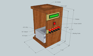
  As opposed to Lee's horizontal design, I opted for a vertical shape due to limited shelf space. I also added removable front panels for the binding posts and display and status LEDs for both ease of assembly and expansion of functionality later on. An intake fan at the top was also integrated to bring in cool air as well as to act as a dummy load for the supply, which is essential for it's operation. The only thing not included in the schematics is the handle at the top, as that particular (and very valuable) detail was suggested by my dad halfway through construction. The Sketchup files can be obtained here.


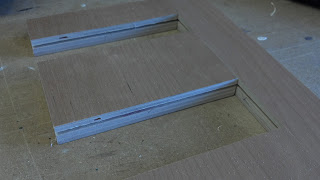
  The building phase was much more time-consuming and intensive than I had imagined, and I became very grateful for my dad's experience in carpentry. It turns out wood is a messy material to work with. I would always emerge from each building session covered in a fine layer of sawdust. Numerous steps had to be taken for each cut of the wood, and I have tried to cover as many of these as I could in the attached photos. After sanding and staining each of the resulting pieces, the box was finally assembled with glue followed by screws. The removable panels were cut from a Lexan sheet and then spray-painted on the back side. Metallic grills were stapled to the insides of the input and output vents. The whole process took about a week of on-and-off work, which was much longer than I had expected. The quality of the product, though, is very high.


  The next step is to finish the wiring of each of the different supply rails to the binding posts. I have some 6 amp fuses and clips for additional short-circuit protection, and I still need to order some proper terminals and appropriately gauged wire to finish this phase. Even further down the road, I would like to learn to program an AVR to drive the LCD display at the top to show exact voltages and currents from each rail, and maybe a digital adjustable output system as well. Stay tuned.