Welcome to BotBakery, a blog that focuses on my personal work with software, electronics, robotics, and any other interests that I might pick up in the future. Posts will serve as overviews of completed projects, short updates on ongoing projects, or simply musings on ideas that might become projects. The occasional rant may also sneak in from time to time.
To tell the truth, I had established this site and registered the domain named for quite a while before finally forcing myself to publish this inaugural post. The main reason for this was that I was reluctant to launch this blog without having a completed project to show off first. I had previously designated my ATX bench power supply conversion to be the showpiece, but as I began another phase of that project last night, I realized that I rarely ever consider any of my work to be "complete" and that I just might as well throw this post up with the photos that I've already acquired.


I admit, an ATX bench power supply conversion is not a very original idea, but I figured that it would serve as a good starting point for me as I begin to take a deeper personal interest in electronics. I had also recently acquired a used 250 Watt ATX supply from Microcenter during the previous Black Friday for ten dollars and was also without any bench supply to speak of (except for a small collection of wall-warts). In addition, I gained inspiration from Ian Lee's post on Software & Sawdust. I had neither the skills nor materials to make a handsome case such as his, but my dad did, so I spent much of my winter vacation working with him to bring clean DC power to my workshop.
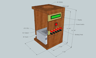

As opposed to Lee's horizontal design, I opted for a vertical shape due to limited shelf space. I also added removable front panels for the binding posts and display and status LEDs for both ease of assembly and expansion of functionality later on. An intake fan at the top was also integrated to bring in cool air as well as to act as a dummy load for the supply, which is essential for it's operation. The only thing not included in the schematics is the handle at the top, as that particular (and very valuable) detail was suggested by my dad halfway through construction. The Sketchup files can be obtained here.


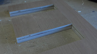


The building phase was much more time-consuming and intensive than I had imagined, and I became very grateful for my dad's experience in carpentry. It turns out wood is a messy material to work with. I would always emerge from each building session covered in a fine layer of sawdust. Numerous steps had to be taken for each cut of the wood, and I have tried to cover as many of these as I could in the attached photos. After sanding and staining each of the resulting pieces, the box was finally assembled with glue followed by screws. The removable panels were cut from a Lexan sheet and then spray-painted on the back side. Metallic grills were stapled to the insides of the input and output vents. The whole process took about a week of on-and-off work, which was much longer than I had expected. The quality of the product, though, is very high.


The next step is to finish the wiring of each of the different supply rails to the binding posts. I have some 6 amp fuses and clips for additional short-circuit protection, and I still need to order some proper terminals and appropriately gauged wire to finish this phase. Even further down the road, I would like to learn to program an AVR to drive the LCD display at the top to show exact voltages and currents from each rail, and maybe a digital adjustable output system as well. Stay tuned.
No comments:
Post a Comment